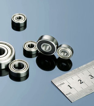
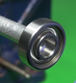
Get out the surgical gloves when working around the most fragile of bearings. Dynaroll miniature ball bearings make a dime look large. (Left)Grooves make room for adhesive to flow without raising runout. (Right)Make sure the shoulder rim clears the opposing ring when locating a bearing against a shoulder in a mating part: Maximum shaft shoulder diameter = Outer ring land diameter – clearance Minimum housing diameter = Inner ring land diameter + clearance A clearance of >0.01 in. allows for normal tolerances. Also, make the shoulder corner radius ra less than the bearing fillet radius, r, so bearings fully seat against shoulders. Most bearing catalogs give these specs. Miniature and instrument-sized ball bearings excel in jobs needing predictable levels of torque, runout, and stiffness. Here, tolerances and finishes measured in millionths of an inch boost precision. However, small size and thin raceways make miniature bearings vulnerable to damage from contamination and high handling forces. Bearing makers typically package the units in Class 100 clean rooms after final inspection because even submicron particles can raise torque and noise levels and shorten bearing life. For users, a clean room or laminar flow workbench is recommended but not required for most assembly jobs,…
Limiting speed values for instrument bearings are almost impossible to determine. However, generalizations may be made. Bearing size: Highest speeds may be obtained with the smallest bearing. However, extremely small miniature bearings usually have a thin, weak retainer and their maximum speed is less than medium-size miniatures. Load: Limiting speed is directly affected by the magnitude of applied load. Heavy loads result in a decreased speed capability. Use of a preloaded pair of bearings also decreases allowable speed. Ring rotation: Inner-ring rotation gives higher speed capability. If the outer ring is rotating, limiting speed must be reduced by about one-third. Retainer: Phenolic (and some other nonmetallic materials) — very high speed; crown (hardened steel) — high speed; ribbon (loosely clinched) — low speed; full race — moderate speed; spacers (PTFE) — very low speed. Lubricant: Stiff, mineral-oil grease — high speed; soft, synthetic-oil grease — moderate to high speed; soft, silicone grease — low to moderate speed; mineral oil — high speed; synthetic oil — moderate speed; silicone oil — low speed. Lubricant method: Oil impregnation and grease pack — excellent; oil impregnation — very good; grease pack — good; minimum oil — fair. Machine Design
Bearing torque is the moment required to overcome internal friction to start or maintain rotation of one ring while the other is stationary. Torque or friction generally increases when: Bearing size is increased because a larger ball and retainer must be moved. Load is increased because of greater deformation and resistance to rolling motion. Speed is increased because of increased lubricant drag. Lubrication type is a critical torque factor. Oil-lubricated bearings generally have lower low-speed torque than grease-lubricated bearings. However, grease-lubricated ones may have lower torque at high speeds, particularly if a channeling grease is used. High-viscosity oils have a higher torque than low-viscosity ones. Bearing design also influences torque. Lightweight metal and molded plastic retainers have the least torque for low and moderate speeds. Phenolic and sintered nylon retainers have lower torque at high speed. Very low contact-angle or radial-play values show high torque because inherent geometrical errors in the bearing raceway and balls cause erratic variation in stress and, hence, friction level. Very-high contact angles have higher torque levels because of the sliding motion in the ball-to-race contact area. Torque-test levels vary from manufacturer to manufacturer, and even lot-to-lot for one manufacturer. There are three types of bearing…
In some applications, allowable load seriously influences selection. Major variables affecting load capacity are ball size and number and internal geometry of the bearing. Static:犀利士 Primary consideration is given to static ratings. A bearing may be deformed permanently by high loads on nonrotating bearings or severe instantaneous loads on rotating bearings. Radial static capacity for instrument bearings is defined as the load causing a permanent, plastic deformation of 0.001 in. of the ball diameter at the ball-raceway contact. This deformation degrades the smoothness and noise level of the bearing. However, in less critical applications, higher loads can be accommodated. Static thrust-load rating is based on two considerations: 1. Load at which the ball-raceway stress approximates that calculated for the heaviest-loaded ball under the limiting static radial load. 2. Load causing the contact area between the ball and raceway to climb over the edge of the raceway shoulder. Thrust ratings vary with contact angle. Lower ratings will result from either low or high angles. Dynamic: Dynamic load ratings are not directly applicable to life prediction of instrument bearings because little life-test data is available. However, metal-fatigue failure is seldom encountered in instrument applications. Recommended use of dynamic load ratings for instrument bearings is limited…
Even with the most-sophisticated motion controller, designers can still find it difficult to attain precise linear motion unless the mechanical components are appropriately designed for the application. Here are six mechanical and structural factors that affect control-engineering performance. Armed with even with the most-sophisticated motion controller, engineers can still find it difficult to attain precise linear motion unless the mechanical components are appropriately designed for the application. Granted, different markets have varying definitions of precision, from nanoscale levels in the semiconductor industry to the relatively generous 0.01-in. standards seen in packaging or newspaper printing. So the industry and application usually determine the needed level of precision. It’s also important to know the operating environment, because some environments make it more challenging to hit the required target. Even machines equipped with the most-sophisticated motion controllers won’t run with exact precision unless their mechanical components are appropriately specified for the application. Let’s start by considering how to define precision. Precision is a combination of accuracy and repeatability. Accuracy, the discrepancy between a movement’s target position and the actual position, reflects motion targets being approached from different directions (multidirectional). So positioning accuracy is the maximum deviation between the actual and target positionsduring each…
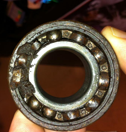
Damaged bearings lead to downtime and lost productivity. Find out how to prevent the damage before it’s too late. The top bearing “killers,” or causes of damage and premature end of bearing life, are inadequate lubrication, contamination, overload, and improper handling and installation. They affect cylindrical, spherical, needle, tapered, and ball bearings. When they strike, they force companies to pay for repairing and replacing both the bearing and adjacent components that get damaged such as housings and shafts. Bearing killers also lower a plant’s operating efficiency, increase downtime, and, in the worst cases, injure workers. Here’s how engineers can monitor and prevent these four bearing killers. OEMs and bearing suppliers typically specify the right lubricant amount, type, grade, supply system, replenishment cycle, viscosity and additives for bearings. They can also help select lubricants for bearings based on history, loading, speeds, sealing, service conditions, and expected life. Manufacturers and distributors should also make detailed recommendations on storage, shelf life, delivery, filtration, and other precautions. And if any conditions change, even those that appear insignificant, the lubricant supplier should be consulted. Inadequate lubrication Inadequate lubrication is the major bearing killer. It can be broken down into eight basic categories: overfilling, underfilling, incorrect…
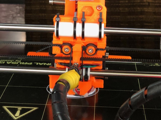
The goal is smooth, jerk-free motion, long-life, durability, and low cost to improve the quality or parts made by 3D printers. Are bearings or bushings best for 3D printers? And how can they be improved so that 3D printers can more quickly and reliably turn out parts of higher quality? Although increasing the quality and speed of 3D printers involves all the components used in them, a good place to start are the bearings and bushings that make up the linear-motion subsystems critical to 3D printers. Bushings and Bearings and Linear Motion In most 3D printers, the build platform (including the extruder) slides over smooth rods as it moves back and forth. The polished rods support the components and guide the extruder along a precise linear path. Bearings or bushings are used on the straight steel rods to reduce friction and smooth out the motion so that it is jerk-free. Bushings, also known as sleeve or plain bearings, are cylinders generally made of bronze, steel, or polymers. These materials reduce friction and the power needed to create linear or rotational motion, as well as to lower noise and wear. Bronze bushings are sometimes impregnated with oil so they are lube-free, or…
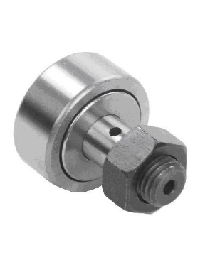
Whether you use cam follower bearings for cam followers, or for track, guide, or support rollers, their performance depends largely on the type you select. Important factors include loads, speeds, misalignment, installation, and lubrication. Cam follower bearings are used mainly in three types of applications: following the surface of a cam, supporting linear motion components, or laterally locating components during linear movement. Of these, cam follower applications range from simple two-dimensional cams to complex three-dimensional indexing cams with multiple followers. Linear motion support applications include platform support rollers and die transfer rollers. Supporting a linear motion component with cam follower bearings reduces sliding friction and track wear. By reducing wear, it also helps maintain precise machine motion. Plus, cam follower bearings guide linear motion components in lateral as well as vertical directions. Basic types Cam follower types include standard stud, heavy stud, and yoke, Figure 1. Both stud types are mounted cantilever-style on a support housing. The heavy stud version is used for heavy loads, shock loading, or applications requiring minimal deflection. Except for the stud diameter and end plate design, standard and heavy stud versions are essentially the same. The yoke version mounts on a pin with a straddle or yoke…
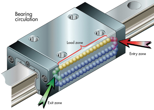
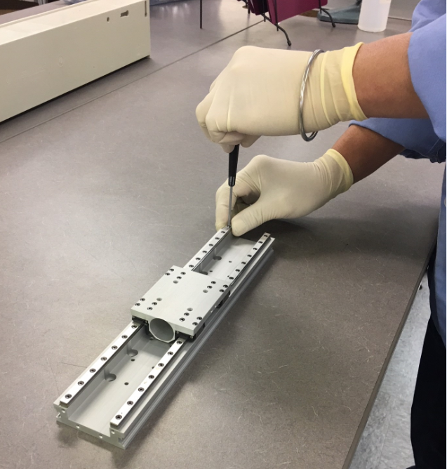
Linear guides are precision mechanical 壯陽藥 assemblies that operate as part of a system. As such, they can only perform to the degree that they are properly integrated into the overall machine. Merely specifying the appropriate guide is not enough. Building a system that operates as intended requires a clear understanding of how to specify, design, install, and test the linear guide. Here, we discuss several of the most common errors made by designers building linear guides into their systems, and ways to avoid them. Not fabricating mounting surfaces to tolerance. Linear guides are precision-ground at the factory to operate with minimal friction. In an ideal world, the friction of each individual linear guide block would be the same whether it is mounted or not mounted. In reality, any misalignment or out of flatness of the mounting surfaces directly adds preload into the linear guide system. Mounting tolerances encompass both the flatness of the mounting surface to which the rails get mounted and the parallelism of the linear guides to one another. If the friction in a guide increases when the assembly is installed, or is more extreme at one end of travel than the other, the mounting tolerances or…
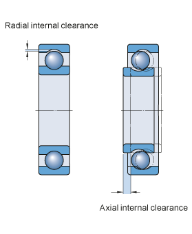
Internal Clearance Internal Radial Clearance of ball and roller bearings is an important parameter in obtaining proper machine operation, optimal bearing life, and a reasonable operating temperature. It is the total distance one bearing ring moves relative to the other radially (radial internal clearance) or axially (axial internal clearance). Categories Initial internal clearance: in the bearing prior to mounting. Mounted clearance: in the bearing after mounting but prior to operation. Operating clearance: in the bearing when it is in operation and has reached a stable temperature. Ideally, for optimum bearing life and machine reliability, bearing internal clearance is zero or slightly negative at operating conditions. Initial bearing clearance is chosen during machinery design and bearing selection to reach this goal. And the bearing manufacturer establishes it by controlling bearing internal structure–roller dimension & groove dimension of IR & OR. Current Standards GB/T4604.1-2012 [Equal ISO5753.1-2009]: Radial ball bearing–radial clearance GB/T4604.2-2013 [Equal ISO5753.2-2010]: Four-point-contact ball bearing–axial clearance GB/T25769-2010: Measuring methods for radial internal clearance GB/T28698-2012: Deep groove ball bearings for electric motors—Specifications GB/T32324-2015: Measuring methods for axial clearance of four-point-contact ball bearing
