Linear guides are precision mechanical 壯陽藥 assemblies that operate as part of a system. As such, they can only perform to the degree that they are properly integrated into the overall machine. Merely specifying the appropriate guide is not enough. Building a system that operates as intended requires a clear understanding of how to specify, design, install, and test the linear guide. Here, we discuss several of the most common errors made by designers building linear guides into their systems, and ways to avoid them.
Not fabricating mounting surfaces to tolerance. Linear guides are precision-ground at the factory to operate with minimal friction. In an ideal world, the friction of each individual linear guide block would be the same whether it is mounted or not mounted. In reality, any misalignment or out of flatness of the mounting surfaces directly adds preload into the linear guide system.
Mounting tolerances encompass both the flatness of the mounting surface to which the rails get mounted and the parallelism of the linear guides to one another. If the friction in a guide increases when the assembly is installed, or is more extreme at one end of travel than the other, the mounting tolerances or rail alignment are very likely out of spec.
Not including mounting features for alignment. Precision linear guides require proper alignment to ensure performance to specification. Particularly in a volume manufacturing scenario, adding mounting features can speed the installation process and ensure effective performance. These can be as simple as a pair of alignment pins that help align the primary rail, coupled with an assembly procedure for aligning the secondary rail.
Applications with very high accuracy performance require more care. Linear guides as delivered from the factory are straight but may still demonstrate a certain degree of compliance. In order to ensure effective operation, guides should be installed using precision shoulder surfaces (Fig. 1). These surfaces provide a flat, stable support structure for the bearings and rails to deliver micron-scale straightness and parallelism.
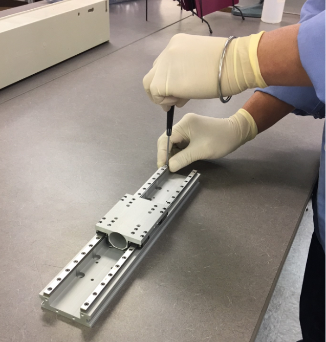
1. To perform as designed, linear guides should be installed on precision mounting surfaces that meet manufacturer tolerances.
It is important to note that error in the parallelism between rails not only affects performance but also service lifetime (Fig. 2). Ensure that rails are aligned to within manufacturer tolerances.
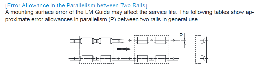
2. Error in parallelism (P) of a linear guide can reduce both performance and service life. Be sure to consult manufacturer specifications before installing.
Mounting shoulders provide essential alignment structures, but they must be properly dimensioned. If the corner radius is too large, the rail may contact the corner radius rather than the shoulder itself during installation and alignment. This can introduce a small but significant error. Worse, it can be very difficult to detect.
The best solution is to specify the shoulder dimensions properly from the start. Manufacturers list very precise specifications for shoulder heights and corner radii in their catalogs, and those should be followed exactly (Fig. 3). Dimension the appropriate corner radius versus the chamfer that is on the bearing.
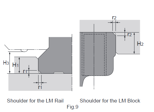
3. Mounting shoulders should be dimensioned, and tolerance as specified in the catalog.
Not specifying preload correctly. Preload in a linear guide involves choosing the diameter of the balls in micron increments to adjust the fit between the block and the rail. In precision applications, it is typically beneficial to have some positive preload, which means that there is no clearance between the block, the rail, and the ball. Depending on the application, the balls may even undergo some compression. Properly specified, preload can reduce negative factors such as vibration, noise, heat generation, and deflection. Improperly specified, however, preload can significantly increase friction and degrade system performance.
It is easy to assume that buying a high-precision linear guide with preload will deliver the best performance. This is true if the precision of the mounting surfaces matches the precision of the linear guide. However, if it is not possible to make the mounting surfaces as accurate as the linear guide, having preload in the guide can actually cause problems.
The preload of the linear guide needs to be matched to the accuracy that can be achieved with the mounting parts. If it is not possible to meet the accuracy required by the manufacturer, it is better to choose a linear guide with a line-to-line fit (normal preload), or even a small amount of extra clearance. The extra clearance will allow the guide to take up the misalignment. The guide will no longer have free clearance, but it also will not demonstrate the high friction that would be introduced by installing a preloaded guide into a low-accuracy system.
In some instances, having a low-friction system is the most important requirement. When that is the case, it is best to specify some internal clearance to ensure that the friction is as low as possible.
Not testing over full run of travel. You can’t fix a problem if you don’t know it exists. Linear guides need to be tested after assembly over the full run of travel. If it is not possible to measure parallelism directly, add an inspection step for measuring the push force of the carriage (Fig. 4). The push force should be consistent to within about 20% when moving the guide from end to end. If push force spikes at one point, frequently this will occur at one end of the guide; it may indicate that the rails are out of parallel and they need to be realigned.
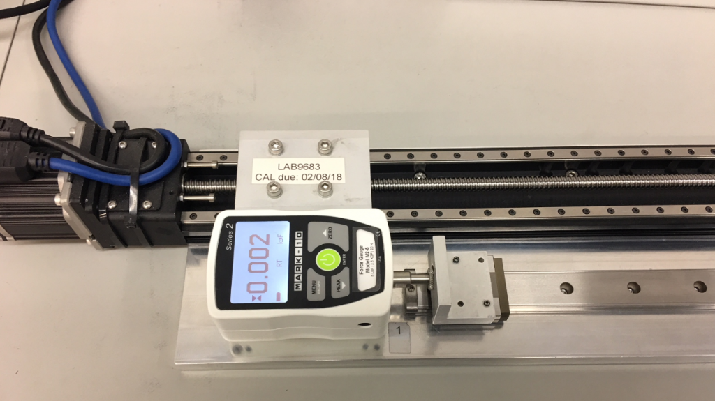
4. A push-force gauge can be used to evaluate the effects of misalignment on the friction of a linear guide. Push force should be consistent to within about 20% over the full distance of travel; a spike may indicate misalignment.
Not considering the effect of materials and plating on cost and lead time. All too often, the effort in specifying bearings focuses on mechanical parameters, while materials and coatings are treated as less important. In reality, materials and coatings can have a significant effect on a project, not just from a performance standpoint but also in terms of cost and lead time. Anticorrosion options, for example, might range from thin, dense chrome plating to various black chrome coatings. In some cases, choosing a stainless-steel version of a linear guide might provide a more effective solution.
The issue is not just one of materials, but also location. Some plating can be performed at an overseas facility while others can be done domestically. A recent order provides an illustration. There is currently a worldwide shortage of certain types and sizes of linear bearings. A customer specified a black-chrome plating for corrosion protection. The problem was that the coating involved had to be applied at our partner’s Japanese factory, which extended the lead time compared to standard product.
After investigation, we recommended an alternative plating. It provided comparable protection, but the difference was that it was available from the partner’s U.S. factory. The switch cut lead time for the parts in half while having minimal effect on cost.
Properly specified and installed, linear guides deliver effective performance in linear motion systems. Be alert for the pitfalls above and your system will be positioned for success.
Machine Design