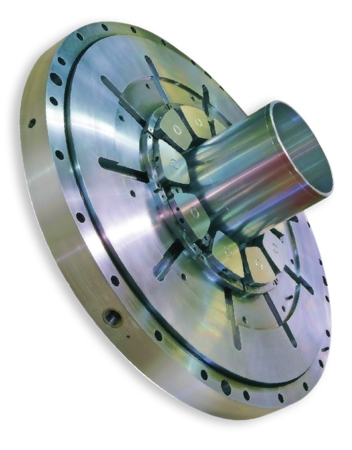
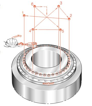
Bearings with diameters between 36 and 169 in. typically cost a lot and have long lead times, forcing end users to keep spare bearings on hand or face extensive downtime should a bearing fail. Therefore, it can make sense to replace a bearing before it degrades. Bearings removed this way often make good candidates for repair or refurbishment. But what qualifies a bearing as repairable? How are repairs carried out? And what kind of results should users expect? Upon receiving a bearing for repair, our company evaluates it and gives the customer a detailed report that suggests one of several approaches. These range from cleaning, verifying clearances, and relubricating the bearing, to replacing major components such as inner or outer races and rolling elements. After cleaning the bearing, we first check the raceway’s integrity by looking for excessive wear or damage. We also measure the surface hardness and perform advanced ultrasonic backscattering to determine the hardened-case depth. These measurements are critical when we must regrind the raceway because enough of the hardened case must remain to support the anticipated ball and roller loads. When customers provide precise loads, we can simply calculate the needed minimum effective-case depth (ECD), usually measured…
Massive rotors in hydroelectric generators, large ball mills, rolling mills, large electric motors, and steam and gas-turbine generators normally operate with great efficiency on oil films in sleeve and thrust bearings. But trouble arises when rotational speed is too low, as it is at starting and stopping, to generate a complete oil film. Then frictional drag and wear increase with metal-to-metal contact between the bearing and rotating shaft. So, how do engineers minimize friction and wear at low speed? The answer is hydraulic lift with pockets that provide oil-film lubrication by lifting a slow-turning shaft off its bearing surface. At low speeds, an auxiliary pumping system with typical pressures of 1,000 to 4,000 psi can float the rotor on an oil film. Once rotational speed reaches the 20 to 30-rpm range, a hydrodynamic bearing operating-fluid film is usually established and can take over the bearing task from the lift pump. To use additional hydraulic lift, designers must carefully calculateoil-feed rates, oil pressures, and bearing lift height. Although the authors suggest engineers follow the general guidelines that follow in both journal and thrust bearings, consulting manufacturer data for specific recommendations is also important. Journal bearings In sleeve journal bearings, pressurized hydraulic…
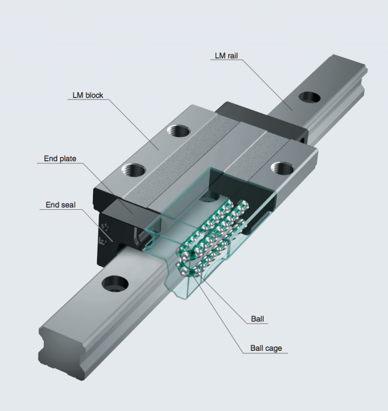
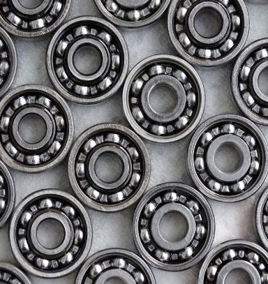
Caged balls offer several benefits, ranging from minimized wear to reduced maintenance. Let’s look deeper into caged balls, their benefits, and design tips for success. Caged balls are widely deployed in motion systems throughout industry. Whether used in ball bearings, linear guides, or ballscrew actuators, caged balls bring both performance and practicality. The addition of the cage minimizes wear, reduces noise, and extends maintenance intervals. The technology also significantly boosts the lifetime of the device compared to non-cage versions. These attributes have made caged balls the go-to technology for a variety of applications. Bearing cages consist of polymer structures that are molded to precise shapes. When the bearing is assembled, the balls are loaded into the cages. The cage surrounds the balls, separating them from one another. Ball cages provide a number of benefits, including: Minimizing metal-to-metal contact Ensuring orderly ball movement Improving high-speed performance Retaining grease for longer lifetime In an extended durability test of THK’s LM guide, a significant amount of the grease originally packed into the bearing (top) remains after the device runs 8,000 km (bottom). (Courtesy of THK) THK developed caged ball technology and is the premier supplier of caged-ball linear guides and ballscrews in the world….
For instrument bearings, certain special considerations should be emphasized: Heavy press fits should be avoided. Accuracy of mounting surfaces should be equal to accuracy of mating bearing surface. Misalignment for low torque and running accuracy should not exceed 1/4°. Loading across the bearing during assembly should be avoided. Axial positioning: Accurate axial positioning of the shaft relative to the housing requires shoulders, snap rings, or bearing flanges. Shaft and housing shoulders: Diameter of a shaft or housing shoulder must be sufficient to ensure solid seating and support for applied thrust loads, yet small enough to avoid interference with other parts of the bearing. Most manufacturers provide recommended shoulder dimensions for each bearing size. Fit accuracy between shoulder and mounting diameter should be as good as bearing accuracy. The corner between the shoulder and mounting diameter should be undercut because undercutting provides a more accurate machining of the shoulder surface. However, a radius is permissible if proper clearance is allowed. Retaining rings: Certain cautions must be observed with this method: Recommendations as to the groove dimensions should be followed. Locating grooves machined into the shaft or housing must be controlled for squareness of groove face to bearing mounting diameter. Recommended value is 0.0002-in. TIR…
Scoring and wiping are two common causes of oil-film bearing failure. Scoring is characterized by circular parallel grooves on the bearing lining surface and are heavier at the load zone. Wiping results in the displacement of babbitt from one location to another. If you see air-moving equipment, chances are oil-film bearings lie at the heart of centrifugal and axial fans. Serious damage can result to the entire unit should these bearings fail. Therefore, it’s important to identify and determine the causes of bearing failure to keep personnel and equipment safe and prevent costly repairs. Oil-film bearings can fail in several ways. These include scoring, wiping, fretting, overheating, fatigue, and corrosion. In industrial fans, the two most-common failure modes are scoring and wiping. Both failure modes can be identified as circular parallel grooves on the bearing-lining surface. Scoring is primarily caused by contamination while wiping develops from displacement of the babbitt. Scoring The severity of scoring is influenced by particles size, bearing load, shaft-surface finish, and speed. The grooves associated with scoring are on the order of 0.001 to 0.040 in. width and depth. The grooves lie primarily over the load zone of the bearing. In oil-film bearings, a converging wedge of oil…
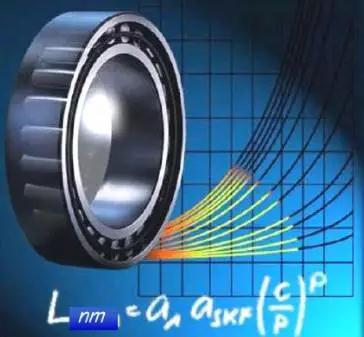
How long will a bearing last? Standardized life equations help to answer. Relative effects of contamination and lubrication condition on bearing life with different load levels. Experience shows seemingly identical rolling bearings operated under identical conditions may not last the same amount of time. In most cases, it is impractical to test a statistically significant number of bearings, so engineers rely on standardized bearing-life calculations to select and size bearings for a particular application. These calculations continue to evolve and become more accurate over time, reflecting the collective experience of the bearing industry, including recent advances in manufacturing, tribology, materials, end-user condition monitoring, and computation. In February of year 2007, the International Organization for Standardization (ISO) published a revised ISO 281:2007 Standard for the calculation of bearing ratings and life. It builds on the previous Standard ISO 281:2000 to account for such factors as internal stresses from mounting, residual stresses from hardening and other manufacturing processes, and material cleanness. Alsoincluded are the effects of solid contaminants with various lubricating systems, as well as bearing material fatigue stress limits. Before going into further detail, it’s probably a good time to review the basics of bearing-life calculations, starting with the common definitions…
Small to midsize OEMs that now source rotating-equipment products and services through multiple vendors may want to consider using a dedicated, local distributor. Distributors have access to a broad product range and can readily supply related items such as bearings, electric motors, belts, and gearboxes. This simple tactic of consolidating your supply source will immediately provide tangible benefits, including one-stop shopping, a single point of accountability, and the preferred services that often come from a close OEM/distributor business relationship. Moreover, distributors can bring the expertise of their suppliers to your organization, including advanced engineering services, ranging from applications engineering, failure and design-life testing, CAD, and vibration/reliability specifications, as well as assembly and warranty information Case in point: A small OEM that builds rope sheaves used in paper-mill dryer sections had recently changed a bearing spec from two single-row, deep-groove ball bearings to a double-row, angular-contact ball bearing. The update looked great on paper, but end users were reporting a significantly shorter bearing service life. The OEM’s distributor brought in SKF to help solve the problem. SKF engineers reviewed the rope-sheave design with computer programs specifically made to analyze bearing operating temperature, loads, raceway positions, and failure modes. The resulting calculations…
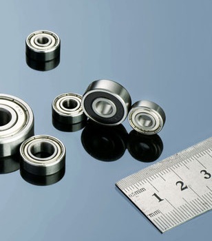
Get out the surgical gloves when working around the most fragile of bearings. Dynaroll miniature ball bearings make a dime look large. (Left)Grooves make room for adhesive to flow without raising runout. (Right)Make sure the shoulder rim clears the opposing ring when locating a bearing against a shoulder in a mating part: Maximum shaft shoulder diameter = Outer ring land diameter – clearance Minimum housing diameter = Inner ring land diameter + clearance A clearance of >0.01 in. allows for normal tolerances. Also, make the shoulder corner radius ra less than the bearing fillet radius, r, so bearings fully seat against shoulders. Most bearing catalogs give these specs. Miniature and instrument-sized ball bearings excel in jobs needing predictable levels of torque, runout, and stiffness. Here, tolerances and finishes measured in millionths of an inch boost precision. However, small size and thin raceways make miniature bearings vulnerable to damage from contamination and high handling forces. Bearing makers typically package the units in Class 100 clean rooms after final inspection because even submicron particles can raise torque and noise levels and shorten bearing life. For users, a clean room or laminar flow workbench is recommended but not required for most assembly jobs,…
Heat is generated either by shearing of the oil film or by rubbing contact. In hydrostatic and hydrodynamic bearings, heat generation at running speeds is the result of oil shear, and the amount of temperature rise can be estimated if oil viscosity and shear rates are known. Temperature can be regulated by controlling the oil flow through the bearing or by using external cooling. Heat is generated either by shearing of the oil film or by rubbing contact. In hydrostatic and hydrodynamic bearings, heat generation at running speeds is the result of oil shear, and the amount of temperature rise can be estimated if oil viscosity and shear rates are known. Temperature can be regulated by controlling the oil flow through the bearing or by using external cooling.DO YOU WANT TO KEEP UP WITHTHE LATEST DESIGN NEWS FOR MANUFACTURING?YES, I NEED TO KNOWNO, NOT RIGHT NOW High-speed and close-clearance fluid-film bearings are difficult to cool. The flow rate through a journal bearing consists of a hydrodynamic portion and a hydrostatic portion. The hydrodynamic flow is proportional to RCw/2 multiplied by a constant which is a function of load or eccentricity e. Here, R = bearing radius, in.; C = clearance, in.; and w = journal speed, rpm. The…
Bearing torque is the moment required to overcome internal friction to start or maintain rotation of one ring while the other is stationary. Torque or friction generally increases when: Bearing size is increased because a larger ball and retainer must be moved. Load is increased because of greater deformation and resistance to rolling motion. Speed is increased because of increased lubricant drag. Lubrication type is a critical torque factor. Oil-lubricated bearings generally have lower low-speed torque than grease-lubricated bearings. However, grease-lubricated ones may have lower torque at high speeds, particularly if a channeling grease is used. High-viscosity oils have a higher torque than low-viscosity ones. Bearing design also influences torque. Lightweight metal and molded plastic retainers have the least torque for low and moderate speeds. Phenolic and sintered nylon retainers have lower torque at high speed. Very low contact-angle or radial-play values show high torque because inherent geometrical errors in the bearing raceway and balls cause erratic variation in stress and, hence, friction level. Very-high contact angles have higher torque levels because of the sliding motion in the ball-to-race contact area. Torque-test levels vary from manufacturer to manufacturer, and even lot-to-lot for one manufacturer. There are three types of bearing…