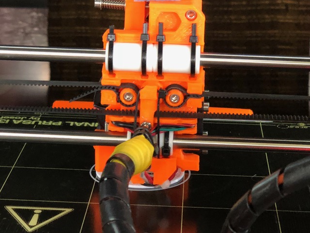
The goal is smooth, jerk-free motion, long-life, durability, and low cost to improve the quality or parts made by 3D printers. Are bearings or bushings best for 3D printers? And how can they be improved so that 3D printers can more quickly and reliably turn out parts of higher quality? Although increasing the quality and speed of 3D printers involves all the components used in them, a good place to start are the bearings and bushings that make up the linear-motion subsystems critical to 3D printers. Bushings and Bearings and Linear Motion In most 3D printers, the build platform (including the extruder) slides over smooth rods as it moves back and forth. The polished rods support the components and guide the extruder along a precise linear path. Bearings or bushings are used on the straight steel rods to reduce friction and smooth out the motion so that it is jerk-free. Bushings, also known as sleeve or plain bearings, are cylinders generally made of bronze, steel, or polymers. These materials reduce friction and the power needed to create linear or rotational motion, as well as to lower noise and wear. Bronze bushings are sometimes impregnated with oil so they are lube-free, or…
The rolling elements in antifriction bearings are critical components that can affect the overall performance of an entire machine. Engineers must consider their many attributes to get the best bearing performance, including: • Diameter and diameter tolerance. • Axial profile • Radial clearance • Surface finish In many cases, catalog data alone does not provide enough information for engineers to confidently specify a bearing and predict performance — particularly in critical applications. Fortunately, some major bearing manufacturers offer application-analysis services that delve deeper into design and operating details. Such analysis considers all bearing inputs and recommends designs or products that deliver the required performance. As an example, let壯陽藥 ’s look at some gearbox bearings. These bearings support a helical gear in a simple planetary set, using two rows of loose needle rollers housed in the bore of the gear. Shaft OD is approximately 0.500 in. and gear bore is about 0.750 in. The unit runs at a maximum speed of 2,300 rpm. Among the areas analyzed:• Loads on the bearing and individual needle rollers.• Contact pressure on the most highly stressed rollers.• Subsurface stress in the raceway, and how it compares to the strength of the raceway material. A free-body…
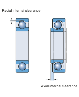
Internal Clearance Internal Radial Clearance of ball and roller bearings is an important parameter in obtaining proper machine operation, optimal bearing life, and a reasonable operating temperature. It is the total distance one bearing ring moves relative to the other radially (radial internal clearance) or axially (axial internal clearance). Categories Initial internal clearance: in the bearing prior to mounting. Mounted clearance: in the bearing after mounting but prior to operation. Operating clearance: in the bearing when it is in operation and has reached a stable temperature. Ideally, for optimum bearing life and machine reliability, bearing internal clearance is zero or slightly negative at operating conditions. Initial bearing clearance is chosen during machinery design and bearing selection to reach this goal. And the bearing manufacturer establishes it by controlling bearing internal structure–roller dimension & groove dimension of IR & OR. Current Standards GB/T4604.1-2012 [Equal ISO5753.1-2009]: Radial ball bearing–radial clearance GB/T4604.2-2013 [Equal ISO5753.2-2010]: Four-point-contact ball bearing–axial clearance GB/T25769-2010: Measuring methods for radial internal clearance GB/T28698-2012: Deep groove ball bearings for electric motors—Specifications GB/T32324-2015: Measuring methods for axial clearance of four-point-contact ball bearing
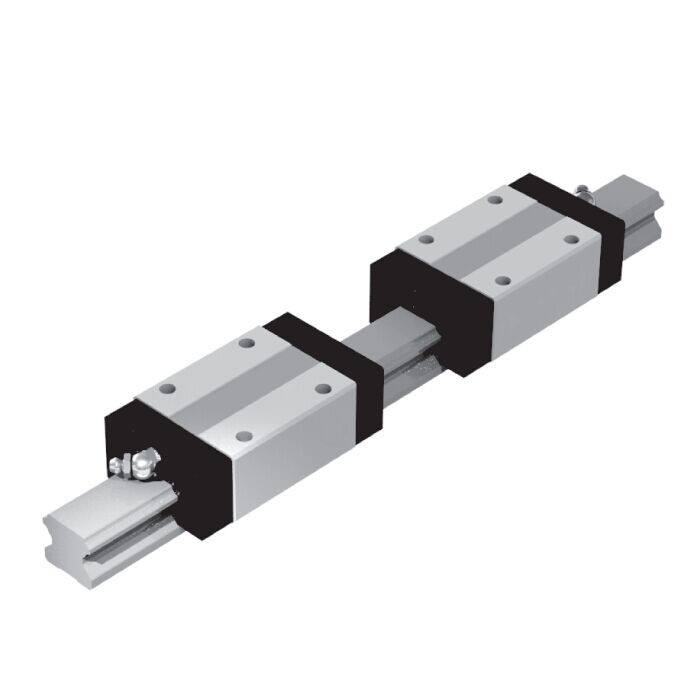
Custom linear bearings can help solve unique problems. Understanding what situations demand a custom linear bearing is key. Each application is a little bit different. For every load that can be perfectly supported by a stock bearing, there are others that require a customized solution. A project may involve specialized environments, extreme performance demands, tight scheduling, and more. Let’s focus on some of the techniques engineers can use to achieve the system characteristics they want. Most of the conversations that we have with people about customization occur when they’re developing a new product and building their first unit. They may have empirically discovered some undesirable characteristic in their system such as excess vibration or a structural element that leans enough to act as an overhung load. Modeling is important, but you can’t really guess what’s going to happen with a high degree of accuracy until you build the system. Designing for Vacuum Clean-room and vacuum applications have very strict requirements for particulate control. Any time components are in motion, you run the risk of generating particles. Grease can minimize friction, and thus particulation, but many formulations outgas, which can compromise the vacuum. Clean-room greases are designed to address both of…
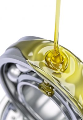
“Bearings are as good as their lubrication”. The lubrication is the most important factor for bearing life. Several actual statistics show that incorrect lubrication causes more than 50% of premature bearing failures.A correct lubrication must cover: 1. The correct lubricant. Oil or grease? Viscosity? Temperature range? Anticorrosive properties? EP properties? Consistency of the grease? Etc. 2. The correct lubrication system. Oil: Oil bath? Oil splash system? Circulating Oil? Oil mist? Air-oil? Etc. Grease: Greased for life? Manual relubrication? Automatic centralized system? Automatic lubricators? Etc. 3. Place for the correct application. Oil or grease must be applied in the correct place so that the flow of the lubricant goes correctly to/through the bearings in the most efficient way. Example: The W33 groove with holes in the outer ring of spherical roller bearings. 4. The correct quantity of lubricant. Excess of lubricant may be as bad as to little lubricant. Excess of lubricant will increase the friction and this will increase the operating temperature which will destroy the lubricant. Lack of lubricant will logically not create the required lubricating film and metal to metal contact will take place in between the rolling elements and the raceways of the rings of the bearings….
Introduction to Six Sigma In today’s information age, news spreads faster than ever. When an event happens halfway around the world it can become common knowledge within hours or even minutes. Companies must guard their reputation for producing quality products. A single, significant quality incident could result in irreparable damage to brand equity and consumers trust. While there are many quality systems in use today, one methodology has gained tremendous momentum and acceptance throughout industry. The foundational elements of this system can be traced back to the 19th century. In the 1920s, Walter Shewert, a renowned statistician, and sometimes referred to as “the father of statistical quality control”, demonstrated that when process variation reaches three sigma from the mean or average value, the process requires correction. An engineer working for Motorola named Bill Smith later coined the term Six Sigma. Bill Smith, along with Mikel Harry and Bob Galvin, the then CEO of Motorola, developed a new Quality Management System (QMS) that emphasized the relationship between product performance and the corrections required during manufacture. Their four phase system became the basis on which the current Six Sigma methodology was built. The four phases were Measure, Analyze, Improve and Control. What is Six…
Introduction to Failure Mode and Effects Analysis (FMEA) There are numerous high-profile examples of product recalls resulting from poorly designed products and/or processes. These failures are debated in the public forum with manufacturers, service providers and suppliers being depicted as incapable of providing a safe product. Failure Mode and Effects Analysis, or FMEA, is a methodology aimed at allowing organizations to anticipate failure during the design stage by identifying all of the possible failures in a design or manufacturing process. Developed in the 1950s, FMEA was one of the earliest structured reliability improvement methods. Today it is still a highly effective method of lowering the possibility of failure. What is Failure Mode and Effects Analysis (FMEA) Failure Mode and Effects Analysis (FMEA) is a structured approach to discovering potential failures that may exist within the design of a product or process. Failure modes are the ways in which a process can fail. Effects are the ways that these failures can lead to waste, defects or harmful outcomes for the customer. Failure Mode and Effects Analysis is designed to identify, prioritize and limit these failure modes. FMEA is not a substitute for good engineering. Rather, it enhances good engineering by applying…
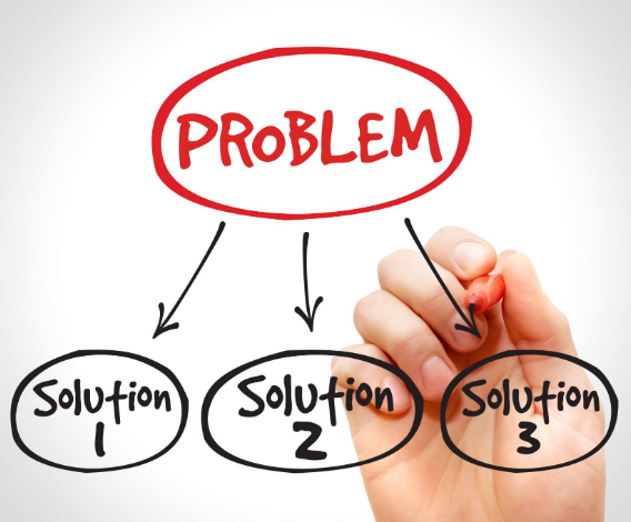
Introduction to Problem Solving In the current world market, consumers and organizations have a vast amount of choices regarding the brand or manufacturer of products, parts and materials available to them. In order to not merely survive but thrive in this ever increasingly competitive market, an organization must provide the most value and the highest quality possible. Most organizations have effective quality systems in place. Unfortunately, we cannot always prevent or detect problems before they reach the customer. Whether your customer is a Tier 1 automotive manufacturer or the end user, problems sometimes occur. Even the companies held up as benchmarks for quality in their industry eventually encounter problems with their product or process. The most important factors at that time are how timely and effectively the problem is resolved and prevented from re-occurring. Problems happen so we must be skillful and systematic in resolving the problems as they arise. What is Problem Solving Problem Solving is the process undertaken to find solutions to complex or difficult issues by taking an analytical approach using scientific methods. Effective problem solving requires the issue to be recognized and fully understood by the problem solver(s). Then, various problem solving methods and tools can…
Introduction to Corrective Action Preventive Action (CAPA) When illness strikes and we need medical attention, we put our trust in the medical products and care givers to provide relief. We expect the care we receive is without fault. Fortunately, failure is not experienced frequently in healthcare and medical devices. When failure does occur, we demand a rigorous process of investigation be initiated to identify why it occurred. Corrective Action Preventive Action (CAPA) is a process which investigates and solves problems, identifies causes, takes corrective action and prevents recurrence of the root causes. The ultimate purpose of CAPA is to as犀利士 sure the problem can never be experienced again. CAPA can be applied in many disciplines. A few of these disciplines are: Manufacturing Product Design Testing Verification and Validation Distribution, Shipping, Transport and Packaging Use-Applications What is Corrective Action Preventive Action (CAPA) Corrective Action Preventive Action (CAPA) is the result of a US FDA requirement, FDA 21 CFR 820.100. The CAPA requirement applies to manufacturers of medical devices and compels them to include CAPA in their Quality Management System (QMS). CAPA is split between two distinct but related functions. Corrective Action (CA) is an extension of Root Cause Analysis (RCA). The first goal…
Now we have the correct equipment for the corresponding application and now comes the turn to the installation. An incorrect installation can reduce the useful life of an equipment due to premature failure caused by several defects. The effects are shown in the following graph: The most common errors in the installation of equipment that reduce the life of the bearings are: 1. Misalignment of the shaft in relation to the driving equipment. Perfectly aligned shafts avoid unnecessary loads on the bearings.It is very easy to detect alignments with vibration analysis and then confirm this cause by means of an analysis of the bearing failure.To avoid this cause of failure there is a large number of aligning instruments on the market that use lasers that are very precise and nowadays very friendly and easy to use without further training. 2. Unbalance. An unbalance also generates unnecessary loads that will cause premature bearing failures. To verify the balance, a vibration analysis must be used, which is able to detect this type of defect very precisely. 3. Mechanical looseness. This problem has increased lately because the designs are increasingly optimized by downsizing, which makes them lighter and less rigid. This defect in…
