Get out the surgical gloves when working around the most fragile of bearings.
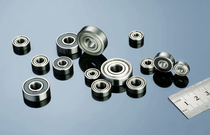
Dynaroll miniature ball bearings make a dime look large.
(Left)Grooves make room for adhesive to flow without raising runout. (Right)Make sure the shoulder rim clears the opposing ring when locating a bearing against a shoulder in a mating part: Maximum shaft shoulder diameter = Outer ring land diameter – clearance Minimum housing diameter = Inner ring land diameter + clearance A clearance of >0.01 in. allows for normal tolerances. Also, make the shoulder corner radius ra less than the bearing fillet radius, r, so bearings fully seat against shoulders. Most bearing catalogs give these specs.
Miniature and instrument-sized ball bearings excel in jobs needing predictable levels of torque, runout, and stiffness. Here, tolerances and finishes measured in millionths of an inch boost precision. However, small size and thin raceways make miniature bearings vulnerable to damage from contamination and high handling forces.
Bearing makers typically package the units in Class 100 clean rooms after final inspection because even submicron particles can raise torque and noise levels and shorten bearing life. For users, a clean room or laminar flow workbench is recommended but not required for most assembly jobs, provided certain precautions are taken.
Keep it clean
Never handle miniature bearings with bare hands. Lubricant protects internal raceways but skin acid can attack unprotected outer surfaces. Keep bearings in the original packaging until use and never leave them exposed to the environment. Handle bearings with talc-free finger cots or surgical gloves. Assembly workers should use only clean, burr-free tools and wear clean-room-spec caps, smocks, and shoe covers, and avoid makeup. Clean work areas and benches daily of dust build up. Finally, wipe mating components with a lint-free cloth, not regular cotton swabs and ordinary cleaning cloths because they tend to introduce lint.
Easy does it
Excessive force during assembly is probably the most common cause of raceway damage in miniature bearings. Such damage contributes to elevated torque and noise levels and short life. Improper handling and interference from poor design or tolerance stack up are the usual suspects.
Miniature bearings have extremely thin inner and outer race cross-sections and turning rings. For bearings sized 0.25-in. OD or smaller, the area under ball grooves (in the races) can be less than 0.008-in thick. Even small forces applied during mounting and assembly may damage these fragile races despite the壯陽藥 ir make-up of relatively hard steel (Rc 60+). In fact, up to 80% of interference with mating components translates into loss of radial play. Standard miniature bearings have a radial play spec between 0.0002 and 0.0004 in., so a total interference of just 0.0003 in. can jam together balls and races. As a rule, spec bearings with a higher radial play or about 0.0005 to 0.0008 in. for interference fits.
Shock or impact loads can also damage miniature bearings, especially when axial play has been removed through preloading. Dropping a preloaded assembly or even placing it on a hard surface can brinnell bearing contact surfaces. To help prevent impact damage cover assembly work surfaces with shock-absorbing materials.
Bearing misalignment during assembly is yet another potential source of high noise and torque levels. Small bearings typically tolerate about 1° of misalignment. Locating-shoulders in mating components must be parallel to bearing raceway faces. Shafts and housings must be concentric to one another, especially when two or more bearings share a common component.
Some preload options
Regardless of component design, bearings need preload to remove axial play and boost axial and radial stiffness. Applying preload to inner rings of bearing pairs maximizes stiffness. Conversely, loading outer rings lowers stiffness. There are three basic preload methods: springs, solid clamping, and deadweight.
Springs press together inner rings or force apart outer races. Springs ease assembly though system stiffness suffers because spring rate rather than raceway-ball elasticity controls stiffness. Springs also minimize relative thermal expansions between mating parts, important for assemblies of different materials exposed to temperature extremes. High-speed applications typically use spring preload as well. For Belleville or wavy-washer springs, tolerance stack up of mating parts can nearly equal maximum allowable compression of the springs themselves. Use a low-rate spring to minimize preload variations.
Solid clamping removes axial play by machining components to precise dimensions. The method produces stiff assemblies and cuts component count. However, normal tolerances in bearing axial play make it difficult to do in practice. Components and bearings must be tolerance matched with high precision or bearings may suffer raceway brinelling (overloading) or have insufficient preload. Precision-matched, duplex-pair bearings solve the tolerance problem but cost significantly more than standard bearings.
The deadweight method preloads bearing pairs with a fixed weight to remove axial play while an anaerobic adhesive securing the bearings cures. Anaerobic adhesives, as the name implies, cure in the absence of oxygen. Therefore at least one mating surface must be oxygen porous to absorb oxygen from the bond. Coated or anodized materials require a suitable primer. Primers may also boost bond strength when bearings and mating surfaces are made of different materials.
In any case, surfaces must be free of grease and oil before applying adhesives. Distribute adhesive evenly around a part circumference, preferably with an electronic dispenser. Any excess adhesive left outside of mating surfaces won’t set properly and may migrate into raceways, causing damage. All visible excess adhesive should be wiped away after setup. Alternatively, use ultraviolet-curing adhesive and expose the excess to a strong UV source after set-up.
Once set-up, anaerobic adhesives have shear strengths on the order of 2,000 to 5,000 psi for push-out forces of hundreds of pounds, even for small assemblies. For maximum joint strength, the gap between mating components must be carefully controlled according to adhesive type. If the recommended gap is excessive for concentricity requirements, then machine grooves in the mating surfaces. This will provide the needed gap and let adhesive flow evenly about the circumference, which boosts bond strength and traps excess adhesive. Be sure to minimize clearance in other mating-surface areas to lower runout. The deadweight/adhesive method gives good control of bearing torque and maximizes stiffness but adhesives take time to cure and require special handling in production.
Machine Design
One Comment
Like!! Thank you for publishing this awesome article.